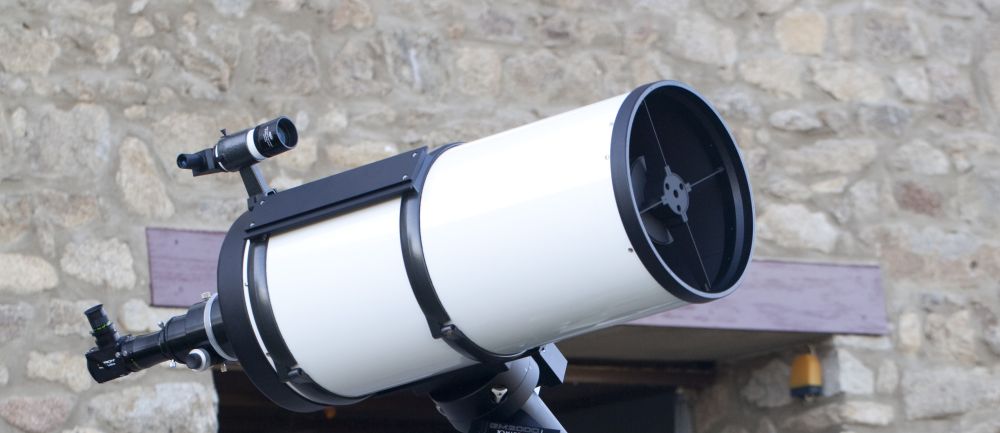
Measuring optical performance of a GSO 12" RC F8 Telescope, on SKY with a natural Star.
This system has been simply inserted into a 2" eyepiece holder / focuser, from a GSO 12" RC F8 and aimed toward a star located nearby the Zenith. The software can stack images automatically to cancel out seeing effects and only measure the optical performance of the whole optics in real conditions, including effects from the mechanical holding the two mirrors. The OTA (Optical Telescope Assembly) must be installed onto a mount which is tracking the stars.
Camera resolution
16 megapixels
Camera frame rate
15 fps (USB 3.0)
Pixel size
3.8 x 3.8 µm
Microlens pitch
110 µm
Amount of spots
130x130 (13200 spots)
Wavelength range
400-900 nm
Aperture dimension
Ø 15 mm
Tilt dynamic range
1000 λ PTV
Measurement repeatability
2 nm rms @ λ=550nm
Absolute accuracy
7 nmrms @ λ=550nm
Camera interface
USB 2.0 or USB 3.0
Operating system
Windows 7,8 or 10
Weight
700g
System F ratio acceptance
F2 to F20
Interface input diameter
Ø 2" or 50.8 mm
System specifications
GSO 12" RC F8 telescope tested in this case.
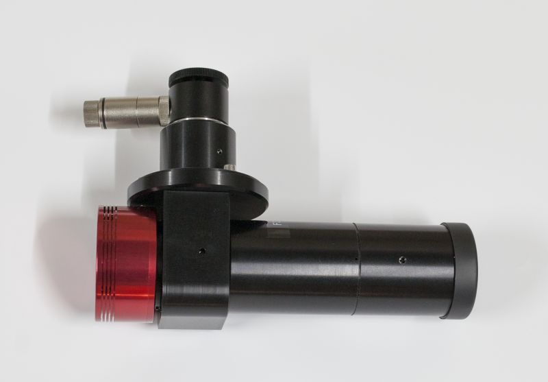
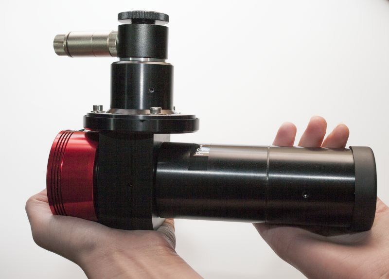
This product is intended to measure accurately optical wavefront (> λ/55) coming from telescopes, refractors or any optical setup.
Or said in a simpler way, it measures the optical performance of optical systems, based on Shack-hartmann wavefront analysis.
The product comes with a 16 megapixel camera and 130x130 microlenses array, a visual aiming system and a set of collimators to acommodate with F number from F/3 to F/20
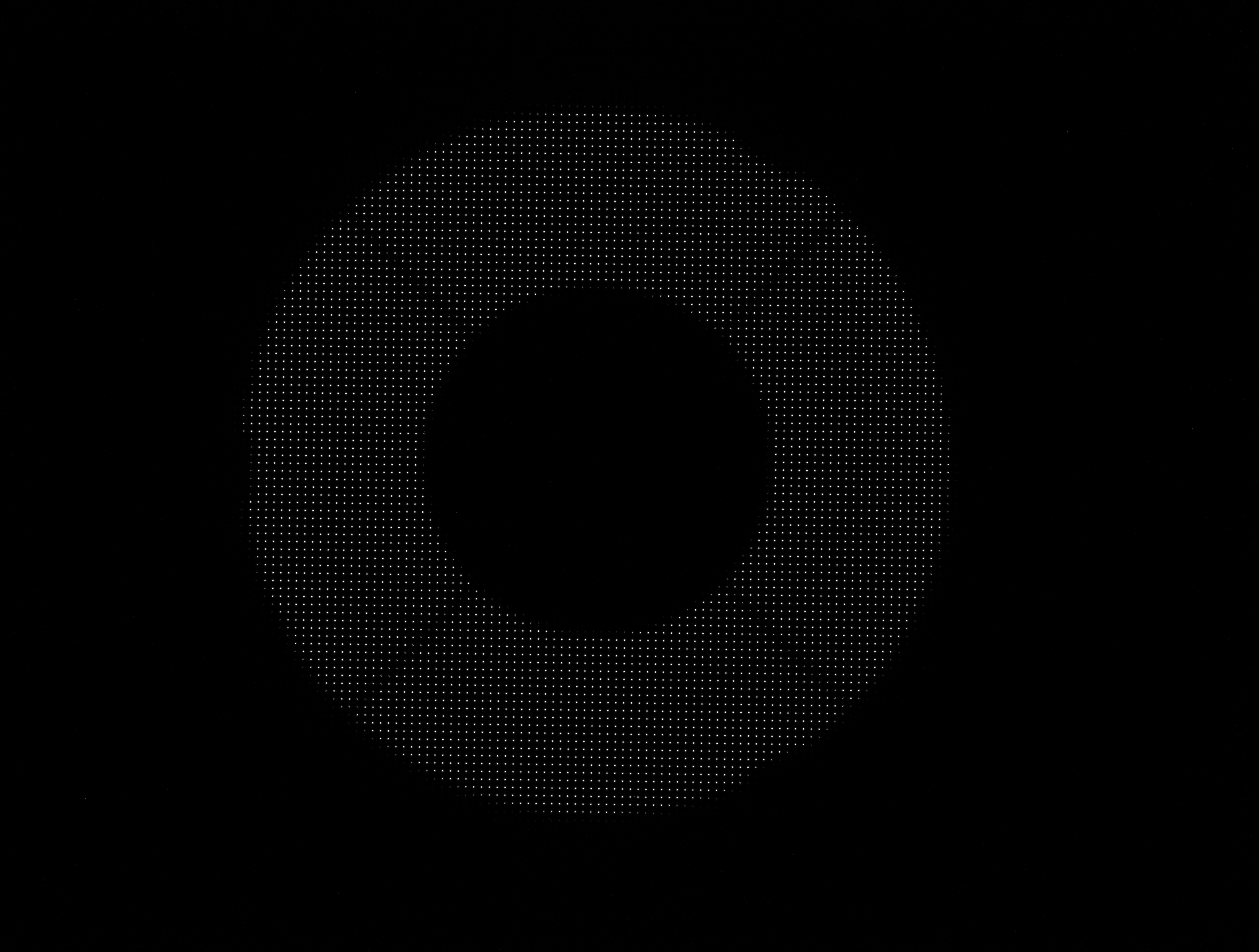
The next picture shows how the spots are laid out in the detector. The pupill size is 2600 pixel diameter and the gap between each spot is 3.4 mm on the main mirror surface. This large sampling rate (8100 spots) allows to retrieve details in the wavefront to extract small errors.
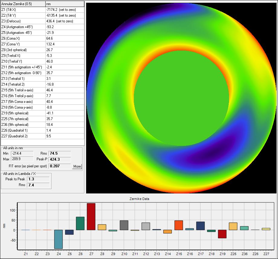
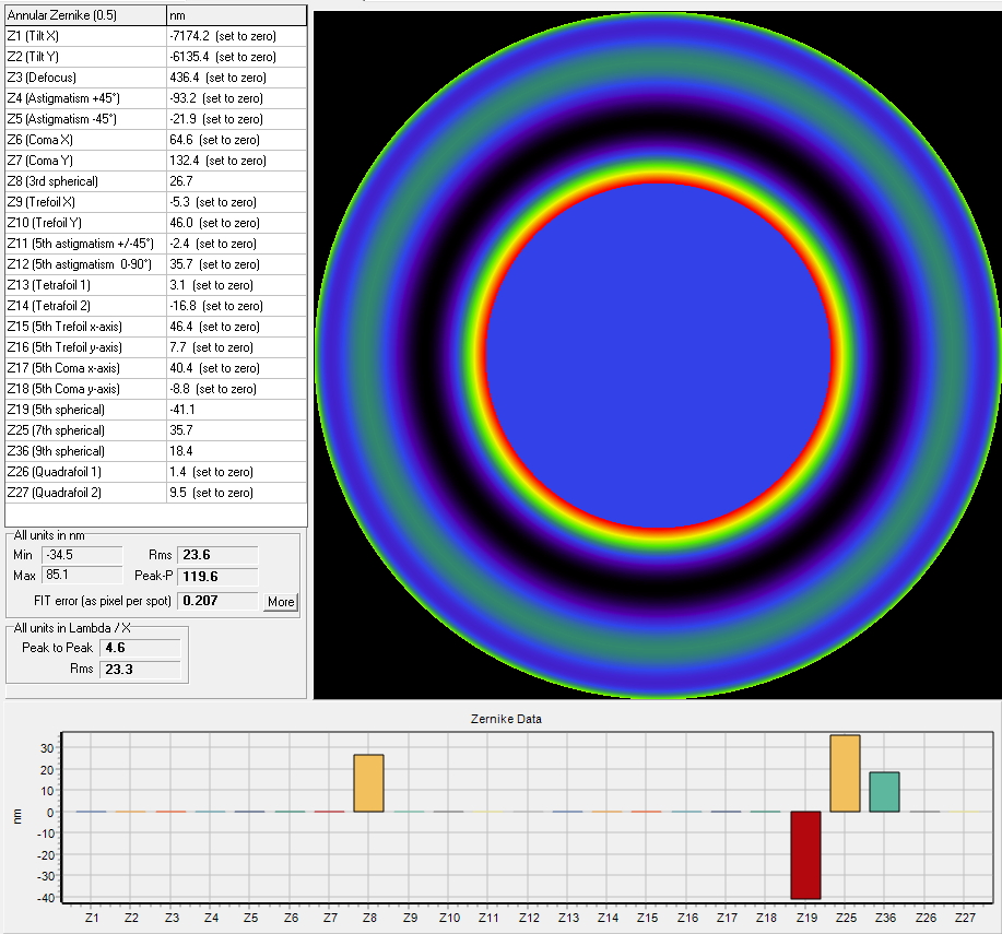
The annular zernikes modal wavefront reconstruction leads to a 75 nm rms error, that is a good performance for this kind of OTA. Some collimation error are visible, Coma X et Y figures give the strength of this collimation error. RC have some astigmatism error due to collimation errors also.
The reconstructed Point Spread Function (PSF) shows how the user would see the star, without any turbulence. The Strehl ratio is 50% taking into account central secondary mirror obstruction.
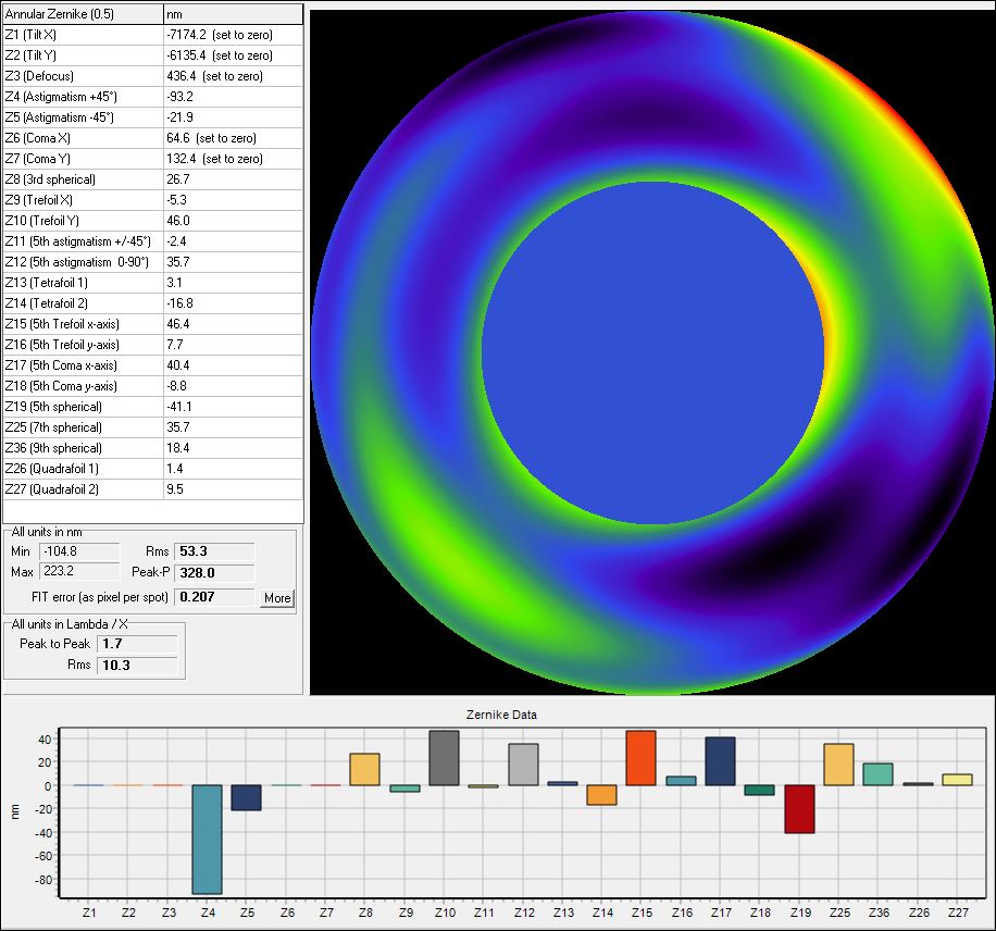
If the coma X and Y are "zeroed", that is like having achieved a perfect collimation, the true performance of the OTA is then measured by the Shack Hartmann. The spherical aberration is almost null, The largest aberration is then some astigmatism that can be due to some collimation errors. The 53 nm rms performance is quite good anyway.
The reconstructed Point Spread Function (PSF) shows how the user would see the star, without any turbulence. The Strehl ratio is 50% taking into account the central secondary mirror obscuration.
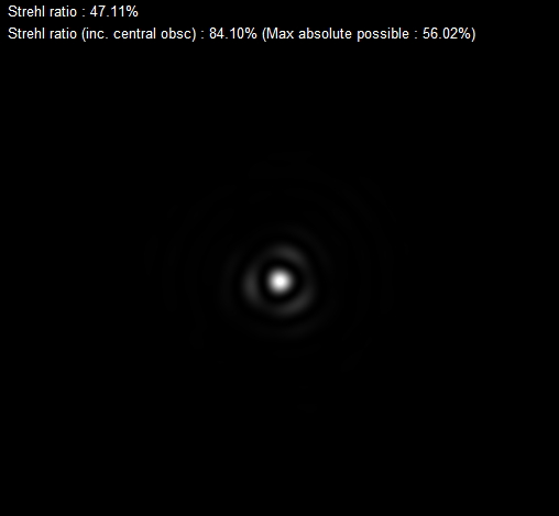
Since the coma X and Y coefficient have been removed / zeroed, the PSF is now almost symetric. The Strehl ratio is now 70%
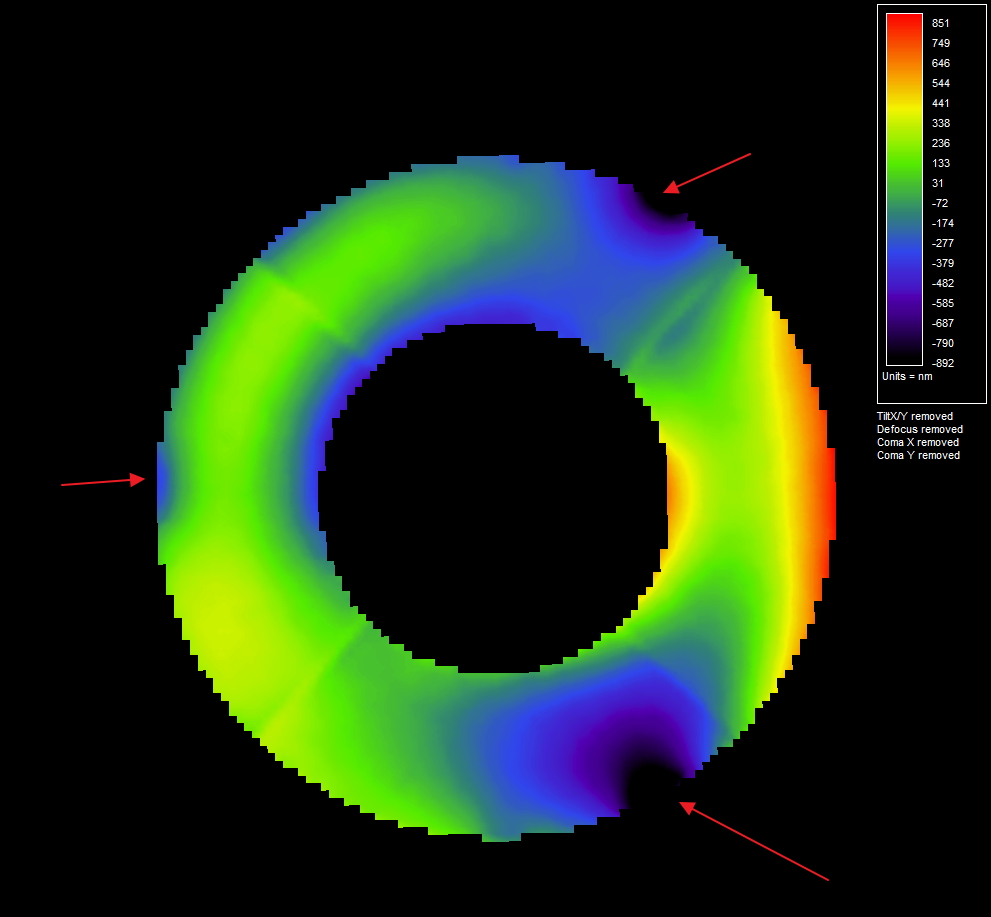
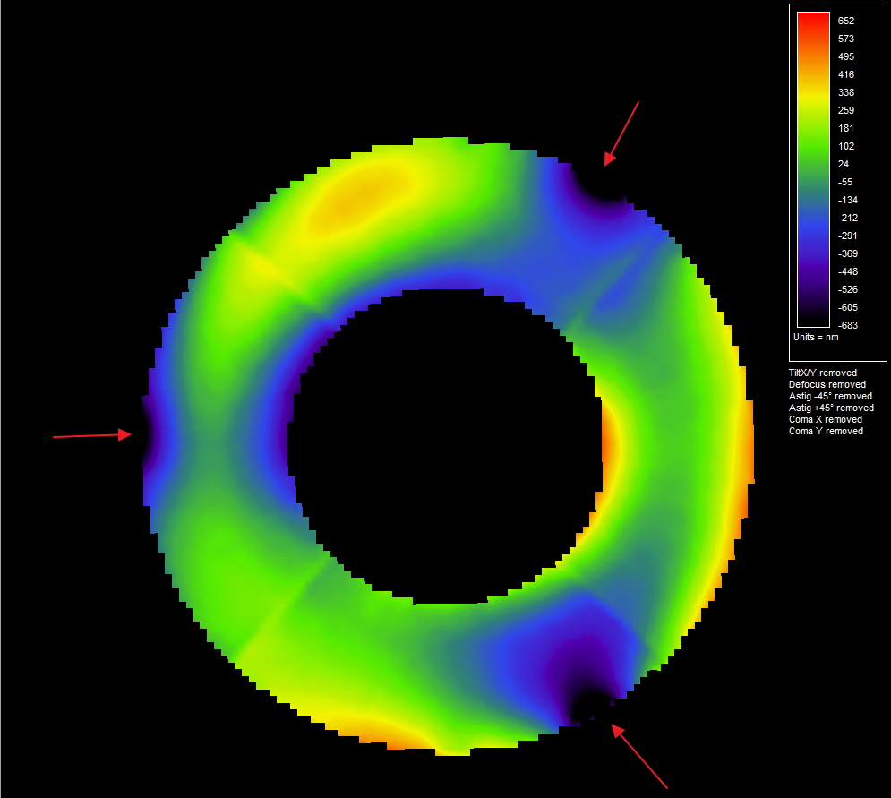
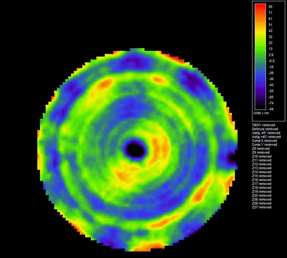
The annular zernike modal analysis is providing information on the shape of the wavefront, but lacks sometime of resolution. Since 8100 spots are illuminated by the pupil, it is possible to perform zonal wavefront reconstruction, that will offer more resolution and some hints on how to improve the optomechanics of the OTA (in this case). The next image is the zonal reconstruction of the GSO 12'' OTA, and the three red arrows show some issue with lateral holding on the main mirror. This latter is pinched by the mechanical system that maintains the mirror in place. It is necessary to release a bit those, in order to relief the main mirror, but this can be at the expense of the optical collimation stability.
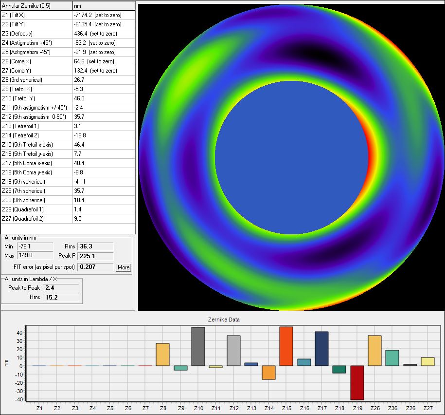
Now, the astigmatism coefficients are "zeroed", This provides more details in the wavefront shape. A lot of trefoild coefficient are now enhanced, confirmin the issue of lateral holding of the mirror.
The Strehl ratio peaks at 85%, which is anyway a very good performance.
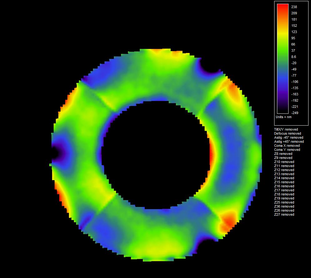
The zonal reconstruction is now even more accurate in displaying the 120° lateral holding system that are too tightened and stress the glass of the mirror. Note : the spider legs are visible in the wavefront, because those spider legs are black and have a different temperature with respect to the ambiant air, and causes some wavefront local errors.
The last outputs are created by removing all non symetric aberrations, just to see the remaining symetrical figuring error of the mirror during polishing process.
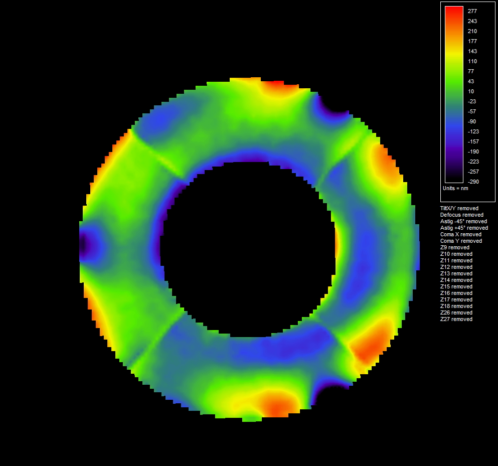
If all 25 first zernikes are removed from the zonal reconstructtion, the next image shows only the high frequencies remaining errors of the wavefront. Spider and secondary mirror holder heat effects are visible.
The symetrical remaining error is very low, say 23 nm rms ! As usual, the zonal reconstruction shows more details.
■
Aiming system that help to center the star (or the image of a 5µm pinhole)
■
Can be used inside auto-collimated system with a flat mirror
■
Color filters can be inserted to measure sphero chromatism
■
Four collimators to get the highest sampling rate for the wavefront
■
USB3.0 camera (Ethernet link on request)
■
Advanced Analysis Software (Zonal and modal wavefront reconstruction, PSF, MTF and much more) USB stick
These figures are computed with a projected pupill diameter on the microlens equal to Ø 13.4 mm
A cooled camera version of this system has been released for long exposures, to maximize detection of low light levels.
Software can be evaluated also in simulation mode, without hardware
Measuring a mirror at center curvature is an usual task in optical workshops. It is mainly performed by the means of knife edge test. Nevertheless the use of knife test leads to wrong or results that are too optimistic, Moreover, this is depending too much on humain perception, such as the sight performance of the user, for instance.
Measuring spherical mirror is straightforward with a Shack-Hartman, but can be difficult for parabolic mirrors due to the huge spherical aberration that is present.
Due to the high dynamic range of the Shack Hartmann, and a good selection of the micro lens arrays, it is possible to perform this kind of measurement using our system. This will relief the user from getting a flat mirror, that is very expensive to cancel the spherical abberation.